

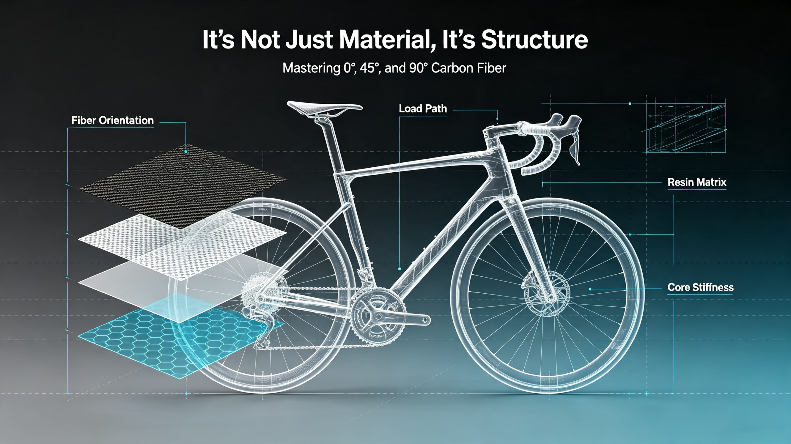
I. Introduction: Carbon Fiber as a “Direction Control System”
Most beginner DIY bike builders fall victim to a pervasive and costly misconception: viewing carbon fiber as nothing more than a lightweight, rigid black plastic material. This oversimplified mindset leads hobbyists to chase premium carbon fiber grades blindly—upgrading from T700 to T800 or M40J—while ignoring the single most impactful factor in frame performance: carbon fiber orientation angles and structured layup design.
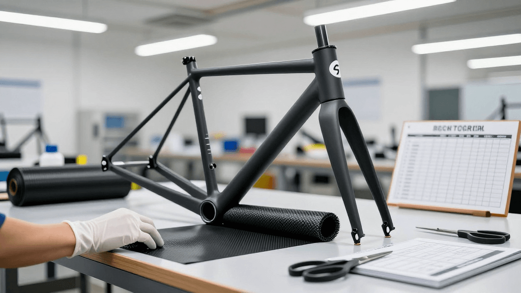
Countless amateur builds result in frames that are light yet flexy, or heavy yet inefficiently stiff, leaving builders confused despite using high-end carbon materials. The issue is never the carbon grade itself; it is the failure to implement a professional carbon fiber layup schedule tailored for bicycle frame structural demands.
The Anisotropic Truth
In professional composite engineering, carbon fiber is not a passive building material—it is an active direction control system that dictates how force travels through a bike frame.
- Steel & Aluminum (Isotropic) : Uniform strength in every direction.
- Carbon Fiber (Anisotropic) : Tensile strength, stiffness, and load resistance exist almost exclusively along the fiber grain. Wood shares a similar directional grain property, but carbon fiber’s directional controllability is precise, customizable, and engineered for performance.
Critical note: Resin only serves to bond fibers together and transfer shear force between plies. All structural load-bearing work is done by the aligned carbon fibers themselves.
Article Roadmap
This article breaks down the professional engineering logic behind carbon fiber stacking sequences for high-performance road bike frames, teaching DIY builders to design by force direction rather than material cost or weight vanity. By mastering the distinct roles of 0°, ±45°, and 90° fiber angles, understanding the difference between UD carbon vs woven carbon, and executing zonal layup optimization (including targeted bottom bracket reinforcement), any builder can construct a frame with superior bike frame torsional stiffness, better power transfer, and balanced ride compliance—outperforming generic factory frames and haphazard DIY builds alike.
II. The First Principle: Assigning Jobs to Different Angles
To master DIY carbon frame construction, builders must abandon the habit of laying carbon plies randomly or using uniform fiber angles across the entire frame. Professional carbon layup design follows one non‑negotiable first principle: assign specific mechanical jobs to specific fiber angles.
Every angle serves a unique structural purpose, targeting tension, compression, torsion, shear, or hoop stability. A well-balanced layup schedule is simply a deliberate ratio of directional fibers working in tandem to handle the full spectrum of real‑world cycling loads.
Below is the core mechanical division of labor among the three foundational fiber orientation sets.
A. 0° Fibers: The Longitudinal Engine (Tension & Compression)
- Definition: Run parallel to the length of frame tubes.
- Analogy: High‑tensile steel cables.
- Primary Loads Handled: Longitudinal tension and compression—the primary loads generated during climbing, steady‑state riding, and hard sprinting.
- Physics in action: When a rider pushes down on the pedals, the down tube stretches under tension; when landing from a descent, the frame undergoes compressive bending.
- Consequence of failure: Without properly aligned 0° fibers, the frame cannot maintain baseline rigidity or efficient power transfer.
Material Preference: 0° layers almost exclusively use UD carbon (unidirectional carbon fiber) . Unlike woven carbon, UD carbon concentrates 100% of its strength along a single direction, delivering maximum longitudinal stiffness with minimal weight penalty.
Professional Allocation:
- 40% – 60% of total ply count dedicated to 0° UD carbon—making it the most abundant angle in any performance frame.
- Key placement zones:
- Down tube: Anti‑tension support.
- Top tube: Controlled vertical bending resistance.
B. ±45° Fibers: The Structural Chassis (Torsion & Shear)
- Definition: Paired bidirectional plies working in opposition.
- Analogy: The chassis or backbone of the frame.
- Primary Loads Handled: Torsion and shear resistance.
- Why they matter: Every pedal stroke generates rotational torque at the bottom bracket; every steering input creates twisting force at the head tube; every uneven road surface induces lateral shear across frame joints.
- Consequence of failure: Without sufficient ±45° coverage, the frame twists like a soft candy bar—wasting pedaling power, dulling steering response, and creating unstable handling at high speeds.
Mechanism: ±45° bidirectional plies work in paired opposition to neutralize shear and torsion in both clockwise and counterclockwise directions. This orientation is the sole reason stiff race frames resist twisting while retaining subtle vertical compliance.
Professional Allocation:
- 30% – 40% of total layup layers dedicated to ±45° fibers.
- Key placement zones (high‑torque) :
- Bottom bracket shell.
- Head tube.
- Front triangle junctions.
Mastering ±45° stacking is the single biggest upgrade for DIY builders looking to eliminate “dead flex” and improve power transfer efficiency.
C. 90° Fibers: The Structural Hoop (Transverse Stability & Crush Resistance)
- Definition: Run perpendicular to tube length.
- Analogy: Tightening barrel hoops that prevent tube expansion, bursting, or lateral crushing.
- Primary Loads Handled: Hoop strength and transverse structural stability for hollow carbon tubes.
- Contribution: 90° fibers contribute almost zero longitudinal stiffness or torsional resistance. They solve unique failure modes that plague poorly designed DIY frames.
Critical Functions:
- Preventing seat tube crushing under seat clamp tension.
- Reinforcing head tube lateral stability during sharp steering maneuvers.
- Maintaining round tube geometry under uneven compressive loads.
Professional Allocation:
- 10% – 15% of total ply volume—serving as structural insurance rather than performance reinforcement.
- Builder warning: Avoid overusing 90° layers, as excess transverse fiber material adds unnecessary weight without improving ride stiffness or efficiency.
III. Engineering Strategy: Zonal Optimization
The second critical principle of professional carbon fiber stacking sequences is zonal layup optimization. Beginner builders often apply identical layup schedules and fiber ratios across every frame tube, creating uniform but inefficient performance. Professional frame engineering rejects uniform layup design entirely.
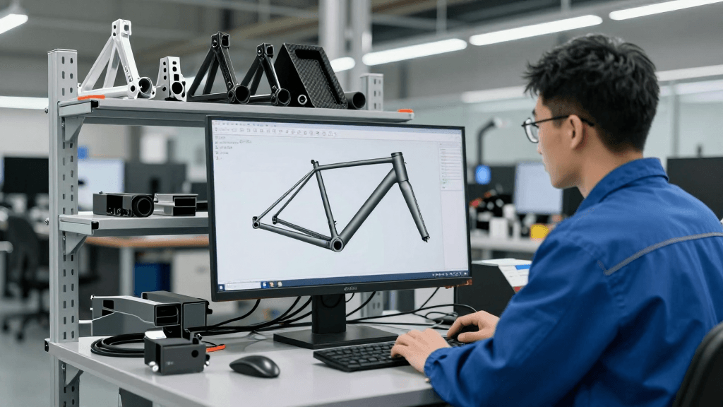
Different frame zones endure completely different load types, force magnitudes, and stress cycles—each requiring a unique layup schedule and targeted fiber orientation mix.
The payoff: Strategic asymmetric reinforcement prioritizes high‑stress performance zones and lightweight optimization in low‑stress zones, delivering a superior stiffness‑to‑weight ratio compared to generic uniform builds.
Below are the three core zonal optimization strategies adopted by professional frame manufacturers.
Zone 1: Bottom Bracket – The Power Plant Reinforcement
The Challenge:
The bottom bracket (BB) is the frame‘s power core, where all rider pedaling force converts into forward motion. This zone faces simultaneous extreme longitudinal tension, compressive bending, and high‑frequency torsional shear stress.
The Design Goal: 100% energy transfer with zero flex loss.
The Amateur Mistake:
Lightening the BB area to cut weight. This destroys torsional rigidity and creates massive power waste.
The Professional Strategy:
Professional engineers intentionally add 30–50g of targeted material here as a performance investment, not excess weight.
| Reinforcement Component | Purpose |
|---|---|
| High‑modulus 0° UD carbon | Maximum bending stiffness. |
| Thick, multi‑layer ±45° stacking | Resist pedaling torsion. |
Performance Outcomes:
- Eliminates BB twist under 1000W+ sprint loads.
- Maintains consistent power transfer.
- Prevents long‑term fatigue cracking at high‑stress junctions.
The minor weight gain in this zone delivers disproportionate performance gains, making it the highest‑return structural upgrade in any DIY frame build.
Zone 2: Head Tube – The High‑Speed Stability Cockpit
The Challenge:
The head tube and front triangle govern steering precision, high‑speed stability, and descending confidence. This zone is dominated by dynamic torsional loads from steering input, crosswind pressure, and high‑speed road vibration.
The Design Goal: Uncompromising torsional rigidity and directional stability.
The Amateur Mistake:
Treating the head tube the same as the seat stays—using a generic layup that fails to lock down front‑end twist.
The Professional Strategy:
Optimal head tube layup prioritizes:
- Dense, continuous ±45° fiber wrapping around the entire head tube junction.
- Balanced 0° longitudinal layers to maintain vertical stiffness.
Critical Technique: Builders use continuous spiral layup sequences here to eliminate ply termination stress points, creating a unified rigid structure that resists multidirectional torsion.
Unlike the BB zone, the head tube requires no excess longitudinal material—only precise angular fiber alignment to lock in handling accuracy.
Performance Outcomes:
- Eliminates vague steering.
- Provides instant corner response.
- Delivers stable handling on rough descents.
Zone 3: Rear Triangle – Tuned Stiffness and Vertical Compliance
The Challenge:
The rear triangle is the frame‘s built‑in suspension system, requiring a deliberate balance of stiffness for power transfer and vertical compliance for ride comfort. Uniform layup design ruins this balance, creating either a harsh, fatiguing ride or a flexy, power‑losing rear end.
The Professional Strategy:
Professional zonal optimization splits rear triangle design into two distinct strategies:
A. Chainstays – Maximum Rigidity
- Load handled: Direct pedaling torque and longitudinal bending loads.
- Layup priority: Favors high‑density 0° UD carbon with moderate ±45° shear layers to maintain torsional stability during hard sprints.
- Goal: Eliminate power loss.
B. Seatstays – Vertical Compliance
- Load handled: Road vibration and micro‑impacts.
- Layup priority: Reduce rigid 0° fiber content, increase flexible ±45° layer ratios.
- Additional tuning: Pair adjusted layup schedules with flattened tube profiles to fine‑tune vertical flex.
The Result:
This targeted mismatch creates a “stiff pedaling platform + compliant ride system” —the hallmark of a high‑performance road frame that is both fast and comfortable over long distances.
IV. The Sandwich Model: Professional Stacking Sequences
Many DIY builders assume carbon layup is simply stacking fibers in random order until reaching the desired tube wall thickness. This approach produces:
- Inconsistent strength.
- Hidden delamination risks.
- Unpredictable flex behavior.
Professional carbon fiber stacking sequences follow a standardized sandwich laminate model—a symmetrical, layered structure that distributes stress evenly, resists impact damage, and eliminates internal structural weaknesses. This industry‑standard layup pattern is used for all primary load‑bearing tubes including down tubes, top tubes, and chainstays. It defines the difference between hobbyist builds and pro‑level frames.
Professional Down Tube Sandwich Layup Structure
(From Outer to Inner Skin)
| Layer Position | Material / Orientation | Function |
|---|---|---|
| 1. Outer Protective Skin | 90° or Woven Carbon Fabric (3K/12K) | Provides cosmetic consistency, surface abrasion resistance, and environmental protection. Shields internal UD layers from scratches, road debris, and moisture intrusion. Not structurally critical for load bearing, but preserves long‑term durability. |
| 2. Core Shear Layer | ±45° Bidirectional Plies | Establishes baseline bike frame torsional stiffness. Locks tube geometry against twisting and shear deformation under dynamic loads. The structural backbone for all torsion‑heavy performance. |
| 3. Primary Load‑Bearing Layer | 0° UD Carbon (Thick) | The primary structure handling longitudinal tension and bending loads. Dictates the frame’s core stiffness‑to‑weight performance—directly influencing climbing efficiency and sprint power transfer. |
| 4. Inner Reinforcement Core | Additional 0° UD Plies | Reinforces the primary load‑bearing structure. Eliminates bending weak points and ensures uniform stress distribution across the tube cross‑section. Prevents asymmetric flex and premature fatigue failure. |
| 5. Inner Closing Skin | ±45° or 90° Plies | Closes the laminate structure symmetrically. Balances the outer shear layers and prevents interlaminar delamination. Symmetrical stacking eliminates internal residual stress that causes frame warping during curing, ensuring perfect geometric stability. |
Why the Sandwich Model Works
This stacking sequence creates a multi‑directional protective structure with built‑in failure tolerance:
- Even if the outer woven skin suffers cosmetic damage or minor impact, the internal 0° and ±45° core layers remain intact.
- Preserves structural integrity and load‑bearing capacity.
- Random layup builds lack this redundancy, meaning small surface damage can trigger immediate catastrophic frame failure.
The symmetrical sandwich is not optional—it is the minimum standard for any frame intended for real‑world road use.
V. Material Selection: Mixing T700, T800, and M40J Carbon Grades
The Common Myth
A pervasive DIY carbon build myth claims that higher‑modulus carbon fiber (M40J, M55J) is universally superior for all frame applications.
The Engineering Reality
In professional material engineering, modulus is only one performance metric. Toughness, impact resistance, and fatigue resilience are equally critical.
| Carbon Grade | Strength / Stiffness | Toughness / Impact Resistance | Best Application |
|---|---|---|---|
| M40J (High Modulus) | Exceptional static stiffness. | Inherently brittle—fractures easily under sudden shock loads. | Mid‑section of long, straight tubes (down tube, top tube) where pure bending stiffness is required without complex shear or impact stress. |
| T700 / T800 (Standard Modulus) | Excellent ductility and fatigue life. | High impact resistance—absorbs sudden shock loads without delaminating or fracturing. | High‑stress joint zones, tube ends, and impact‑prone areas: head tube, BB shell, seat tube clamp region. |
The Professional Hybrid Strategy
Professional builders adopt a hybrid material strategy that balances stiffness, durability, and cost efficiency:
- T700/T800 → Deployed at joints and impact zones for toughness and long‑term reliability.
- M40J → Deployed strategically in the mid‑section of straight tubes for pure bending stiffness, where brittleness risks are minimized.
- Result: A frame that is stiff where needed, tough where it counts, and durable over thousands of kilometers.
The Verdict for DIY Builders
A well‑designed hybrid layup with perfect carbon fiber orientation angles will ALWAYS outperform a poorly laid pure M40J frame.
Material selection is secondary to precise carbon fiber layup schedule design. For all DIY builders, the T700/T800 hybrid layup delivers the optimal cost‑to‑performance ratio.
VI. Conclusion: The Art of Layup
Premium carbon fiber frames are not defined by expensive materials or ultra‑light weight figures—they are defined by intentional, engineering‑driven layup design.
The Three Pillars of Professional Layup
- Master the division of labor:
- 0° longitudinal fibers → Tension & compression.
- ±45° torsional fibers → Shear & torsion resistance.
- 90° transverse fibers → Hoop stability & crush resistance.
- Execute zonal optimization:
- Bottom bracket → Maximum stiffness with 0° + ±45° reinforcement.
- Head tube → Uncompromising torsional rigidity with continuous ±45° wrapping.
- Rear triangle → Stiff chainstays + compliant seatstays for balanced ride quality.
- Balance UD carbon vs woven carbon and hybridize material grades (T700/T800 + strategic M40J) to maximize both performance and durability.
The Outcome
A perfect carbon fiber stacking sequences plan creates a frame with:
- Predictable, tunable riding character.
- Stiffness where power transfer matters.
- Compliance where ride comfort is needed.
- Stability in all road conditions.
The Unanswered Question
While this article establishes the complete structural layup framework for DIY builders, one critical question remains:
Now we have our layup plan. But how do we calculate if it’s stiff enough without building it first?
We need to talk about Stiffness‑to‑Weight Ratio and Finite Element Analysis.
References
Carbon Fiber Anisotropy & Orientation Principles
- Composites World. “The fundamentals of carbon fiber design: orientation and layup.” Composites World, 2020. https://www.compositesworld.com/articles/the-fundamentals-of-carbon-fiber-design — Explains how fiber orientation dictates mechanical properties in anisotropic composites.
- ScienceDirect. “Fiber direction and stacking sequence design for bicycle frame made of carbon/epoxy composite laminate.” ScienceDirect, 2009. https://www.sciencedirect.com/science/article/abs/pii/S0263822309003169 — Identifies optimal stacking sequences [0/90/90/0]s and [0/90/45/−45]s for composite bicycle frames using finite element analysis.
- AZO Materials. “Unidirectional Carbon Fiber vs. Woven Carbon Fiber – A Comparison.” AZO Materials, 2021. https://www.azom.com/article.aspx?ArticleID=20576 — Details the mechanical differences between UD and woven carbon, including strength concentration and weight efficiency.
Zonal Optimization & Frame Zone Engineering
- Covill, D., et al. “An assessment of bicycle frame behaviour under various load conditions using numerical simulations.” Sheffield Hallam University Research Archive, 2016. https://shura.shu.ac.uk/ — Outlines finite element models simulating frame behavior under measured load cases, providing data for zonal stiffness optimization.
- Bike-Room. “Evolve Cima: Analyzing the Lightweight Climbing Frameset.” Bike-Room, 2026. https://bike-room.com/ — Demonstrates zonal layup with high-modulus carbon in BB and head tube for lateral stiffness, while reducing material density in seat stays.
- Specialized. “FACT Carbon Fiber – Layup Schedule Development.” Specialized.com, 2026. https://www.specialized.com/ — Explains that every layup is unique to each bike and frame size; fiber orientation in BB, head tube, and rear triangle is optimized separately.
Sandwich Laminate Stacking Sequences
- ScienceDirect. “Decomposed surrogate based optimization of carbon-fiber bicycle frames using Optimum Latin Hypercubes for constrained design spaces.” ScienceDirect, 2013. https://www.sciencedirect.com/science/article/abs/pii/S0263822313000165 — Discusses symmetric laminate stacking sequences and safety factor constraints for carbon bicycle frames.
- Cube Bikes. “C:68X® – Material & Technology.” Cube.eu. https://www.cube.eu/ — Describes how up to six different fibre types are used in a single frame’s sandwich layup to optimize stiffness and compliance in precise sections.
- Singletracks. “How Carbon Fiber Layup Makes Bike Frames Stiff and Compliant in all the Right Places, with Alchemy.” Singletracks, 2022. https://www.singletracks.com/mtb-gear/how-carbon-fiber-layup-makes-bike-frames-stiff-and-compliant-in-all-the-right-places-with-alchemy/ — Explains the layup schedule determines stiffness at the bottom half and compliance at the top half of the frame.
Carbon Grades: T700, T800, M40J – Properties & Applications
- Toray Composite Materials. “Torayca® Carbon Fiber Data Sheet.” Toray Industries. https://www.toraycma.com/products/carbon-fiber/ — Official specifications for T700, T800, and M40J carbon fibers, including tensile modulus, strength, and strain-to-failure data.
- ScienceDirect. “Predicting the fatigue life of T800 carbon fiber composite structural component based on fatigue experiments of unidirectional laminates.” International Journal of Fatigue, 2024. https://www.sciencedirect.com/science/article/abs/pii/S014211232400481X — Establishes fatigue progressive damage model for T800 carbon fiber, confirming its superior fatigue resistance.
- Palacin, D.J.A., & Salazar, J.L.L. “Material evaluation for the Hardtail MTB Frame of a bicycle to increase its fatigue resistance.” LACCEI, 2024. DOI: https://doi.org/10.18687/LACCEI2025.1.1.444 — Compares carbon grades for bicycle frames, noting M40J’s high stiffness but lower impact toughness compared to T800.
DIY Carbon Frame Construction Techniques
- Rinard, D. “How I Built a Composite Bike in My Garage.” Sheldon Brown’s Bicycle Technical Information. https://www.sheldonbrown.com/rinard/composite.htm — Detailed DIY guide to hand lay-up with unidirectional and woven carbon fiber pre-preg, including practical tips on ply orientation and stacking.
- BikeRadar. “Carbon fibre – how it’s used in bike frames.” BikeRadar, 2013. https://www.bikeradar.com/advice/buyers-guides/carbon-fibre-how-its-used-in-bike-frames/ — Explains how carbon fibre’s anisotropic properties are manipulated in the layup process to optimise rigidity, impact resistance, and torsional strength.
Related Reading
Deciding how to manufacture custom frames? Compare the two sourcing models in OEM vs ODM carbon bike frames, then follow our step-by-step guide to ordering custom OEM carbon frames from China.


[…] Fibre orientation. A frame’s stiffness comes from orienting plies at 0° for bending loads and 45° for torsion, with 90° plies resisting crushing at clamp points. Getting this wrong makes a frame that is stiff in the wrong directions and vague in the right ones. We wrote about the 0°, 45° and 90° layup in detail here. […]